What is a P&ID (Piping and Instrumentation Diagram)?
Understand P&ID easily—decode symbols, read diagrams, and master process flow with this beginner-friendly engineering guide.
Table of Contents
A P&ID (Piping and Instrumentation Diagram) is a detailed drawing used in process industries to show the piping, equipment, valves, and instruments involved in a system. It helps engineers understand how a process works and how it is controlled.
P&ID is also called PEFS (Process Engineering Flow Scheme) in some industries. It is different from a PFD (Process Flow Diagram), which shows only the basic flow and major equipment.
Who Creates a P&ID?
Piping and Instrumentation Diagrams (P&IDs) are primarily developed by process engineers during the design and planning phase of a plant or system. These diagrams serve as the blueprint for process flow, control systems, and equipment layout. Creating a P&ID is a collaborative effort involving multiple disciplines:
Process Engineers
- Lead the development of the P&ID.
- Define the process flow, operating conditions, and safety requirements.
- Ensure compliance with industry standards and client specifications.
Instrumentation Engineers
- Add control loops, sensors, transmitters, and actuators.
- Specify instrument tags, signal types, and interlocks.
- Integrate control philosophy and automation logic.
Mechanical & Piping Engineers
- Select and size equipment like pumps, compressors, heat exchangers, and vessels.
- Design piping routes, supports, and pressure ratings.
- Ensure mechanical integrity and maintainability.
CAD Designers / Drafters
- Use specialized software such as AutoCAD, SmartPlant P&ID, AVEVA Diagrams, or Intergraph to draft the diagram.
- Maintain drawing standards, layer management, and symbol libraries.
- Convert engineering inputs into readable, standardized drawings.
Project Managers & Safety Engineers (Optional but Crucial)
- Review P&IDs for operability, maintainability, and safety compliance.
- Ensure alignment with HAZOP studies and SIL assessments.
- Coordinate revisions and approvals across departments.

Why is P&ID Important in Engineering?
P&ID plays a key role in engineering by linking design, safety, operations, and training. Below are the main reasons why it’s so important in every stage of a project.
- Shows process flow: It clearly displays how fluids and gases move through equipment and pipelines.
- Supports safety analysis (HAZOP): Helps identify risks and plan safety measures before construction.
- Guides maintenance: Technicians use it to locate equipment and fix issues efficiently.
- Enables automation: Control engineers design sensor and loop systems based on the diagram.
- Used for training: New engineers learn plant operations without visiting the site.
- Helps in upgrades: Useful for planning modifications or adding new equipment.
- Improves team coordination: All departments refer to the same diagram for clarity.
- Supports procurement and construction: Helps teams buy the right equipment and install it correctly.
- Useful in audits and compliance: Shows regulators that safety and standards are followed.
What Symbols are used in P&ID?
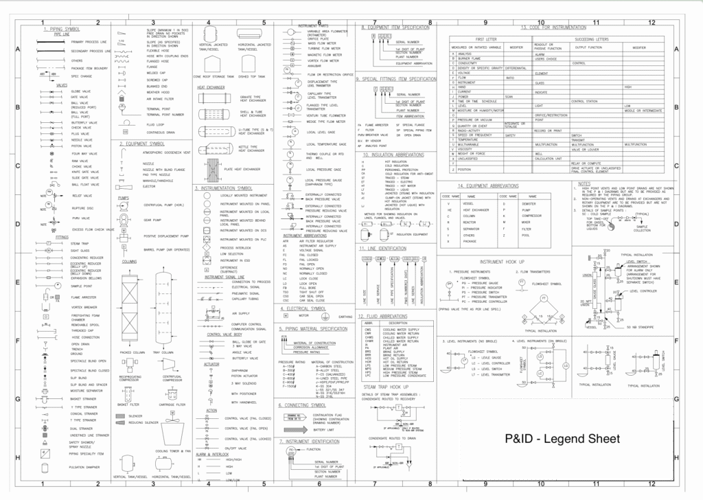
Piping and Instrumentation Diagram use standardized symbols to represent various components in a process plant. These symbols help engineers, technicians, and operators understand the layout and function of the system without confusion.
- Equipment Symbols: Represent machines and devices like pumps, compressors, tanks, heat exchangers, reactors, filters, etc. Each type has a unique shape to distinguish it.
- Valve Symbols: Include gate valves, globe valves, check valves, ball valves, butterfly valves, control valves, and more. Symbols also show whether valves are manual or automated.
- Instrument Symbols: Cover devices like pressure gauges, flow meters, level indicators, temperature sensors, and transmitters. They often include a circle with letters like PT (Pressure Transmitter), FT (Flow Transmitter), etc.
- Line Types: Different lines indicate process flow, instrument signals, pneumatic or electric connections. For example:
- Solid lines for process pipes
- Dashed lines for instrument signals
- Dotted lines for electrical wiring
- Control Loops and Tags: Symbols also show how instruments are connected in control loops, including feedback, alarms, and interlocks. Tags like TIC-101 (Temperature Indicating Controller) help identify function and location.
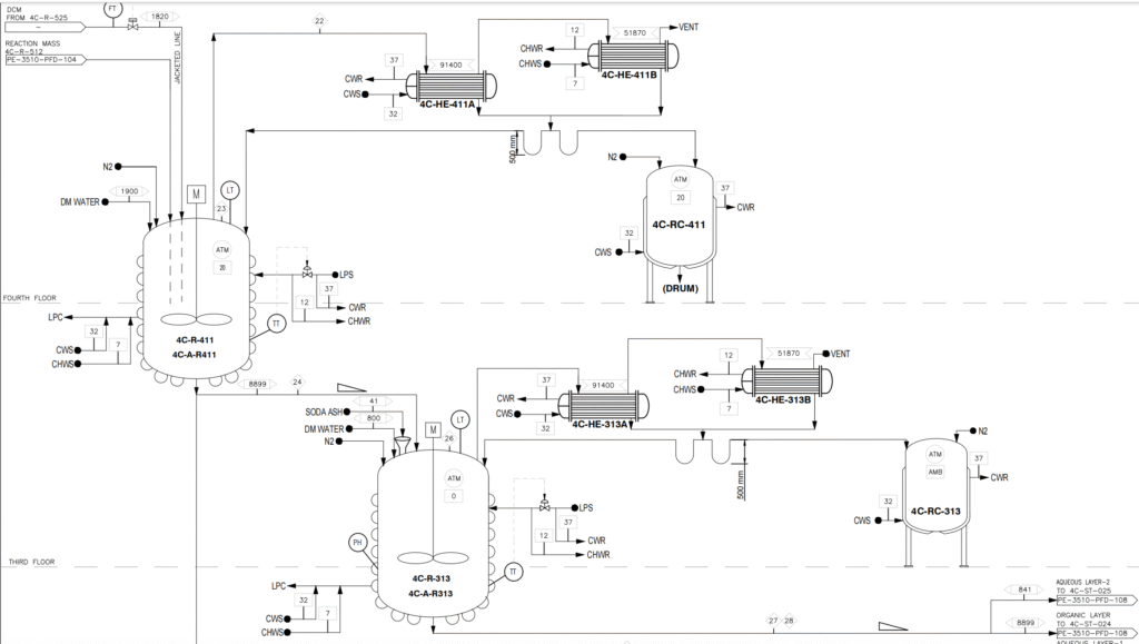
How to Read a Piping and Instrumentation Diagram (P&ID)—Step by Step
- Start from the main line and follow the flow:
Begin at the main process line (usually a thick solid line) and trace the direction of flow. Arrows show where the fluid or gas is going — from one equipment to another. - Identify equipment and understand its function:
Look for symbols of pumps, tanks, heat exchangers, compressors, etc. Each symbol represents a machine. Try to understand what each one does in the process — for example, a pump moves liquid, a heat exchanger transfers heat. - Check valve types and their control logic:
Notice the different valve symbols — gate valve, globe valve, check valve, control valve. Some are manual, some are automatic. Control valves may have actuators and signals connected to them. - Follow instrument tags like PT, FT, TT, LT:
These tags tell you what kind of instrument is used:
- PT = Pressure Transmitter
- FT = Flow Transmitter
- TT = Temperature Transmitter
- LT = Level Transmitter
These help monitor and control the process.
- Understand control loops and interlocks:
Instruments are often part of control loops. For example, a temperature sensor sends a signal to a controller, which adjusts a valve. Interlocks are safety features that stop the process if something goes wrong. - Look for safety systems like alarms and shutdowns:
Check for symbols showing alarms, emergency shutdowns (ESD), relief valves, or safety interlocks. These protect the plant and people from accidents.
Which Software is Used to Create P&ID?
- AutoCAD P&ID
- SmartPlant P&ID
- AVEVA Diagrams
- Lucidchart
Among the leading tools for creating P&IDs—such as AutoCAD P&ID, SmartPlant P&ID, and AVEVA Diagrams—Lucidchart stands out for its intuitive interface, cloud-based collaboration, and ease of use for both beginners and professionals. It allows teams to design, share, and iterate on piping and instrumentation diagrams in real time, without the steep learning curve of traditional CAD software. For those looking to get started quickly, Lucidchart also offers a comprehensive P&ID tutorial that walks users through the process step by step.
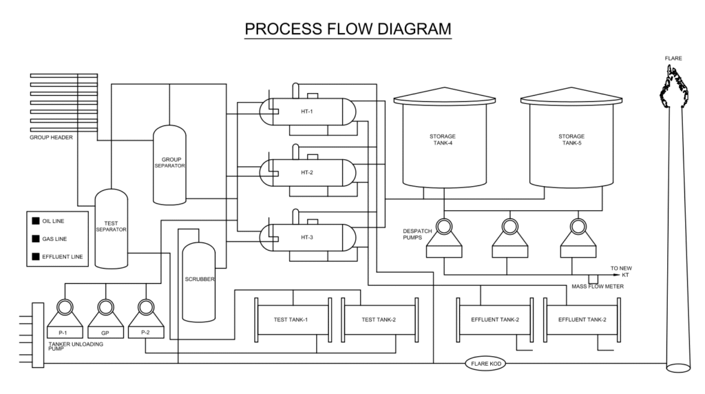
What is the Difference Between PFD and P&ID?
A Process Flow Diagram (PFD) shows the overall picture of how a process works. It includes the main equipment like pumps, tanks, and heat exchangers, and shows how materials move between them. PFDs are used in the early design stage to understand the basic flow and balance of the system. It gives general information like temperature, pressure, and flow rate, but does not show small details.
A Piping and Instrumentation Diagram (P&ID) is more detailed. It shows every pipe, valve, instrument, and control system used in the plant. It helps engineers during construction, operation, and maintenance. P&ID also shows safety systems, alarms, and automation. So, while PFD tells what happens, P&ID explains how it happens in full detail.
Conclusion: Why Every Engineer Should Master the Piping and Instrumentation Diagram
The piping and instrumentation diagram (P&ID) is more than just a technical drawing—it’s the backbone of process engineering, safety planning, and operational excellence. From design to maintenance, P&IDs empower engineers to visualize complex systems, troubleshoot issues, and ensure smooth automation. Whether you’re a student, technician, or seasoned professional, understanding how to read and create P&IDs is essential for success in industries like oil & gas, chemical, pharmaceutical, and manufacturing.
If you’re looking to deepen your knowledge or train your team, explore our process design engineering course. You’ll find tutorials, case studies, and engineering insights tailored to real-world applications—including P&ID interpretation, instrumentation control, and process safety.
Pingback: Instrumentation Design Career: Scope in India and Abroad - Petromech Institute
Pingback: Process Design Engineering Course After Chemical Engineering - Petromech Institute
Pingback: AutoCAD Training in Vadodara – Practical 2D Drafting for Mechanical, Electrical, Chemical & Instrumentation Engineers - Petromech Institute
Pingback: Basic Engineering Package: A Complete Guide for Instrumentation Engineers
Pingback: Why Process Engineering for Production Engineers is the Key to Career Growth - Petromech Institute
This is the kind of quality content I love to see.