Control Systems & Engineering Deliverables: From Architecture to Hook-Up Drawings
In modern industries, Control System Engineering is the brain behind safe and efficient operations. Whether you’re working in oil and gas, chemical, or power plants, understanding control system design and its engineering deliverables is essential. This blog explains everything from architecture and wiring to vendor coordination and layout drawings—perfect for students, freshers, and professionals aiming to master instrumentation design.
Table of Contents
Introduction to Control System
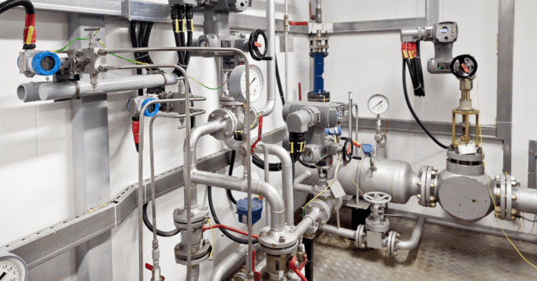
A control system manages process variables like temperature, pressure, flow, and level. It ensures that the plant runs smoothly, safely, and efficiently. These systems monitor inputs from field instruments and send commands to actuators or valves.
Control systems are used in almost every industry—from refineries and chemical plants to power stations. They help maintain stability, reduce manual errors, and improve productivity. Learning control systems is a key part of process engineering and instrumentation design.
Design Considerations in Control Systems
Designing a control system requires careful planning. Engineers must consider process needs, safety requirements, redundancy, and scalability. The system should be reliable and flexible enough to handle future expansions.
Safety is a top priority. Redundant systems are often used to avoid failure. Scalability ensures that the system can grow with the plant. These design considerations form the backbone of automation and are part of every job-oriented engineering course.
Control System Architecture
Control system architecture defines how controllers, sensors, and actuators are connected. It includes devices like PLCs (Programmable Logic Controllers), DCS (Distributed Control Systems), and SCADA (Supervisory Control and Data Acquisition).
A well-designed architecture improves communication between devices and ensures smooth operation. It also helps in troubleshooting and future upgrades. Engineers must choose the right architecture based on plant size, complexity, and budget.
Control System Specifications
Specifications describe the hardware, software, and performance requirements of the control system. They include details like processor speed, memory, input/output capacity, and communication protocols.
These specifications help vendors understand what the project needs. They also guide procurement and installation. Clear specifications reduce errors and ensure that the system meets operational goals.
Wiring in Control Systems
Wiring diagrams show how field instruments are connected to control panels. They include cable types, terminal numbers, and routing paths. Proper wiring is essential for installation, testing, and maintenance.
Bad wiring can lead to signal loss, noise, or even equipment damage. Engineers must follow standards and use quality materials. Wiring is a key deliverable in control system design and must be reviewed carefully.
Loop Diagram in Control System Engineering
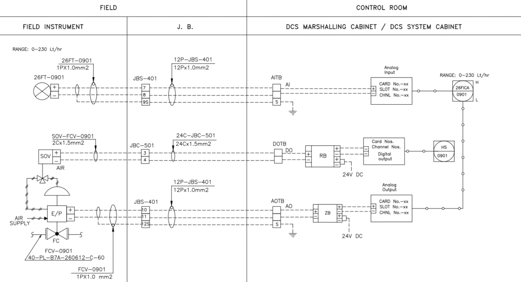
A loop diagram represents the signal path from field instruments to control systems. It shows how sensors send data to controllers and how controllers send commands back to actuators.
Loop diagrams help during commissioning and troubleshooting. They also support documentation and training. Every loop must be tested to ensure correct operation and safety.
Cause & Effect Diagram
The cause and effect diagram shows how one event (cause) triggers another (effect). For example, high pressure may cause a valve to open or a pump to stop. These diagrams are used in safety and shutdown systems.
They help engineers design emergency responses and interlocks. Cause and effect diagrams are reviewed by safety teams and are part of critical control systems.
Alarm Trip Setting List
This list defines alarm thresholds and trip points for process variables. It ensures that operators are alerted in time and that the system shuts down safely if needed.
Alarm settings must be chosen carefully. Too many alarms can confuse operators, while too few may miss important events. Engineers must balance safety and usability.
Control Room Layouts

Control room layouts show the physical arrangement of control panels, operator stations, and display screens. A good layout improves ergonomics and workflow.
Operators must have easy access to controls and clear visibility of displays. Layouts also include lighting, seating, and emergency exits. These designs affect daily operations and safety.
Vendor Offer in Control System Projects
Vendors submit offers based on specifications. These offers include pricing, delivery time, warranty, and compliance details. Engineers review these offers to select the best option.
Vendor selection is not just about cost. It also involves checking technical compatibility, support services, and past performance. A good vendor ensures smooth execution and long-term reliability.
Technical Query in Control System Engineering
Technical queries are raised to clarify vendor offers, specifications, or drawings. These queries help resolve doubts and ensure alignment before finalizing decisions.
Engineers must document queries and responses. This avoids confusion and supports future audits. Clear communication with vendors is key to project success.
Technical Bid Tabulation
This document compares multiple vendor offers. It includes technical scores, commercial terms, and delivery schedules. Bid tabulation helps in selecting the most suitable vendor.
It also supports transparent decision-making and client approvals. Engineers must ensure that all offers are evaluated fairly and consistently.
General Arrangement Drawings (GAD)
GADs show the layout of instruments, panels, and cable trays. They help in installation planning and site coordination. GADs must be accurate and easy to read.
These drawings are reviewed by multiple departments. They ensure that equipment fits properly and that there are no clashes. GADs are part of the final engineering deliverables.
MCT Block in Control Room Design
MCT (Multi Cable Transit) blocks are used to seal cables entering control rooms. They prevent fire, water, and gas from passing through cable openings.
MCT blocks are essential for safety and compliance. They also support cable management and reduce maintenance. Engineers must select the right type and size based on cable quantity and room layout.
Mastering Control System Engineering and its deliverables is a powerful step toward a successful career in instrumentation. From architecture and wiring to vendor coordination and layout drawings, each topic builds your confidence and skills. Whether you’re working in oil & gas, chemical, or power sectors, this knowledge helps you design safe, efficient, and scalable systems.
If you’re looking to learn this in detail with practical examples and real industry insights, join the Instrumentation Design Engineering course at Petromech Baroda LLP. We teach everything—from control systems to Basic Engineering Package—with easy language and hands-on practice. Our course is perfect for freshers and professionals who want to build a strong career in engineering. So don’t wait—visit Petromech Baroda LLP or send us an enquiry today. Your future in instrumentation starts here.
Pingback: Instrumentation Design Deliverables: Index, Hook-Ups, and Vendor Coordination - Petromech Institute